
V-Trac Horn Installation
These installation instructions will guide you through the entire installation of the V-TracII horns and related hardware for the Klipsch Khorn and Belle speakers.
Important Note
Please note – this photo-essay page was developed prior to the introduction of the V-TracII midrange horn, and so all the photographs and references here are made to the original V-Trac. The installation of the new horns is almost exactly the same as the originals. As time goes on, we will edit this page to reflect the few minor details of installing the V-TracII horns.
Introduction
Thank you for your purchase of the V-TracII horns. These installation instructions will guide you through the entire installation of the V-TracII horns and related hardware for the Klipsch Khorn and Belle speakers. Belle owners – please note – photographs here show upgrades being installed in Khorns, but the installation of the upgrades in Belle speakers is very similar. I will note specific differences between the Khorn and Belle installations in the notes below.
V-Trac horns are shipped in product-specific packaging that has proven to be very durable, and we’ve had very few problems so far with shipping damage. However, please inspect the box and contents for damage, and if you do have shipping damage, please let me know asap, and before you install anything so we can put a claim in to the shipping company for reimbursement on the insurance.
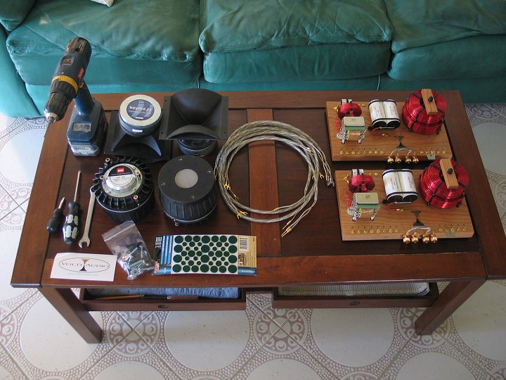
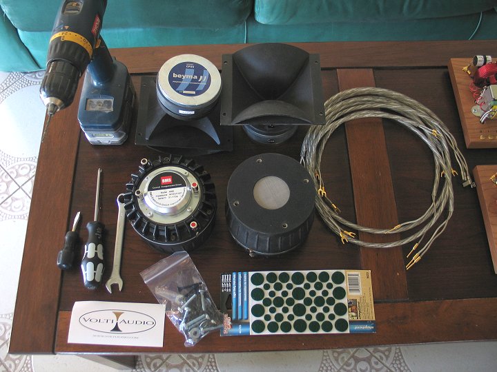
V-Trac horns are shipped with the necessary hardware for installation, and you will find a bag of screws, felts, badges, and tweeter motorboards inside the box along with the horns.
Tools needed include, but may not be limited to, a variety of screwdrivers, a 1/2" box wrench, two pairs of pliers, small adjustable wrench, and perhaps a utility knife.
Unpack all the parts from the box and clean up any packing materials. Save the packing materials and box for future use.
Disassembly
01
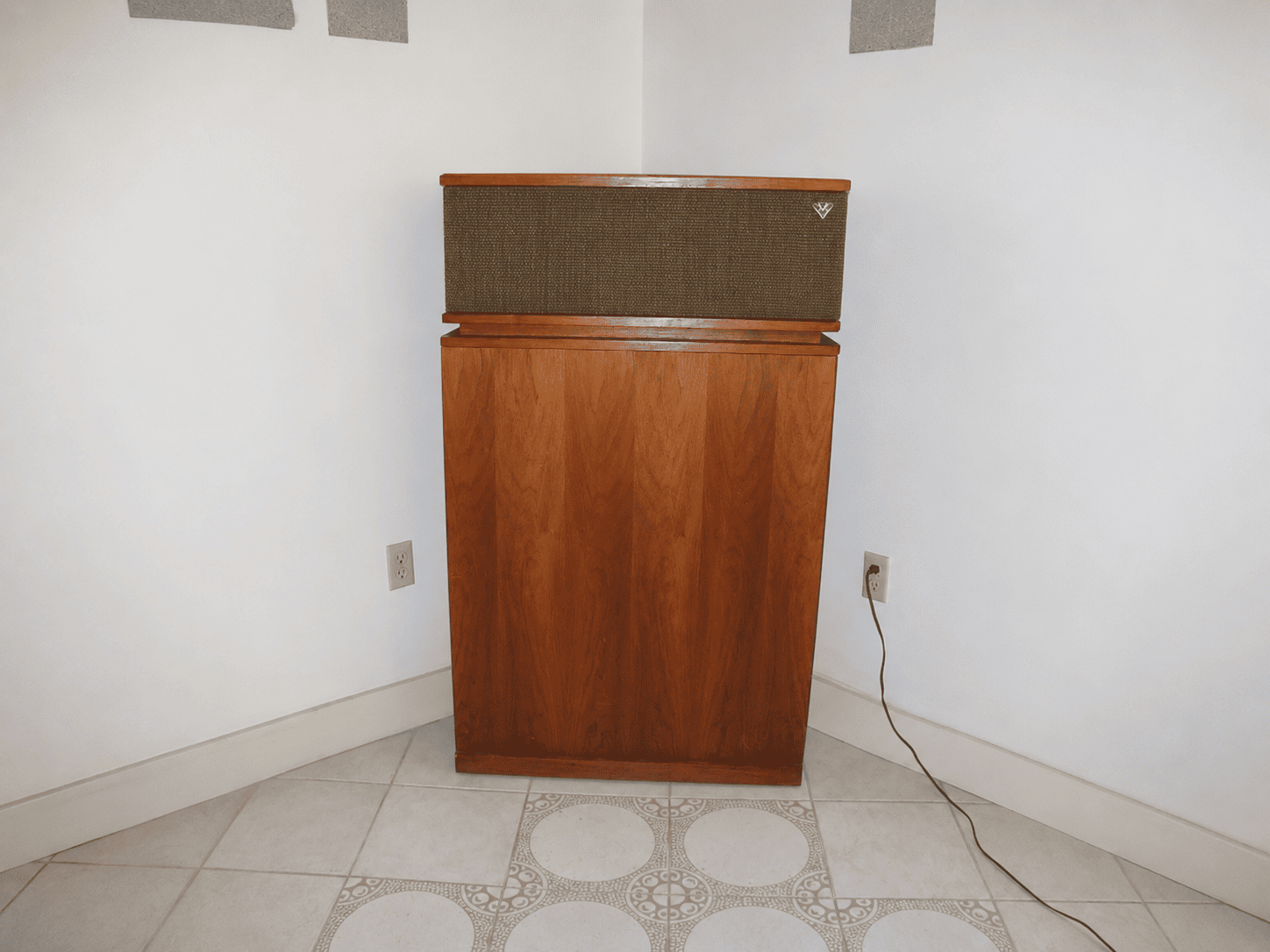
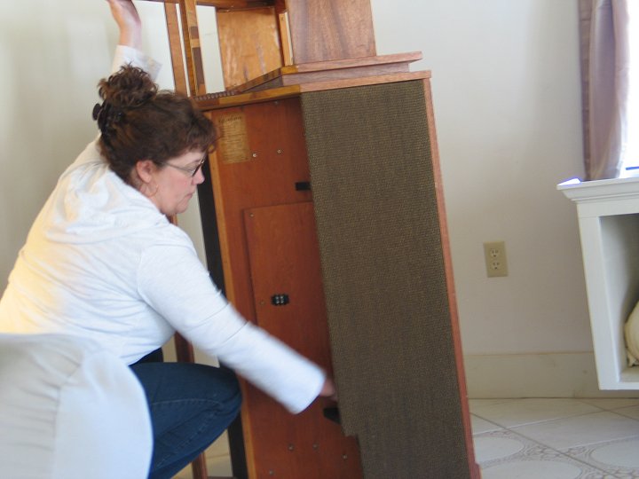
Pull the Khorns out from the corners, and give yourself enough room to work all around each cabinet. If you are replacing woofers, remove the side grill frame on the side of the woofer access door and place out of the way.
02
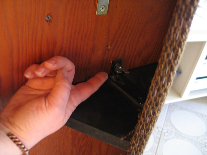
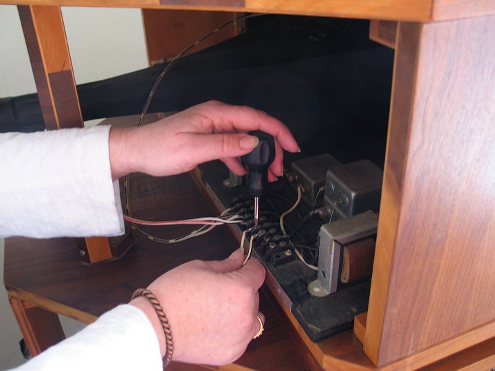
Remove the component wiring from the crossover, the wire from the woofer chamber door, and the crossovers from the cabinets and set everything out of the way.
03
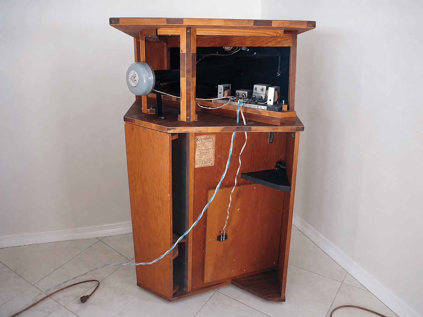
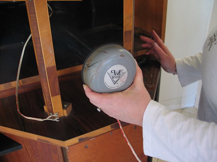
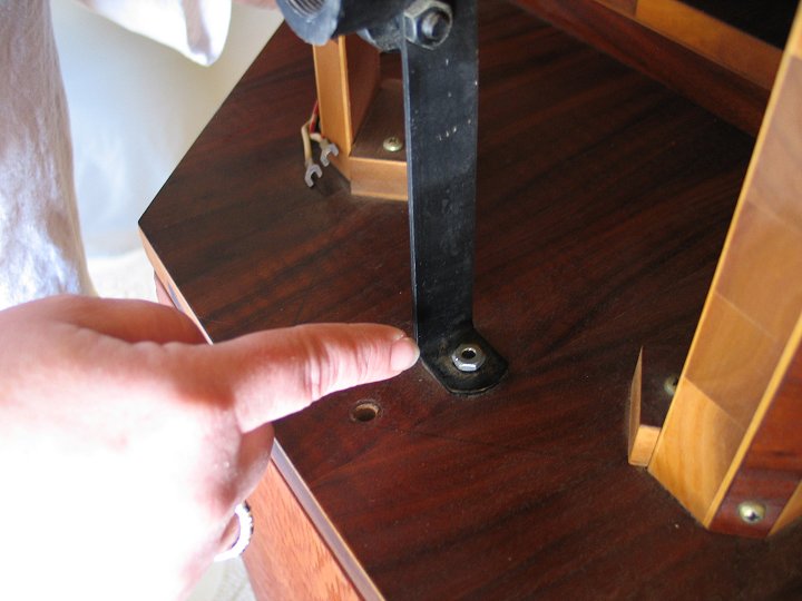
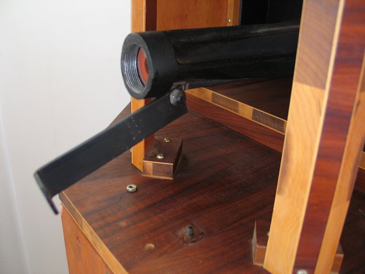
Remove the midrange driver by unscrewing it from the end of the horn. Remove the screw that holds the end bracket of the midrange horn down to the cabinet. Loosen the nut where the bracket is attached to the midrange horn and pull the bracket up and back so it is close to horizontal and in line with the horn.
04
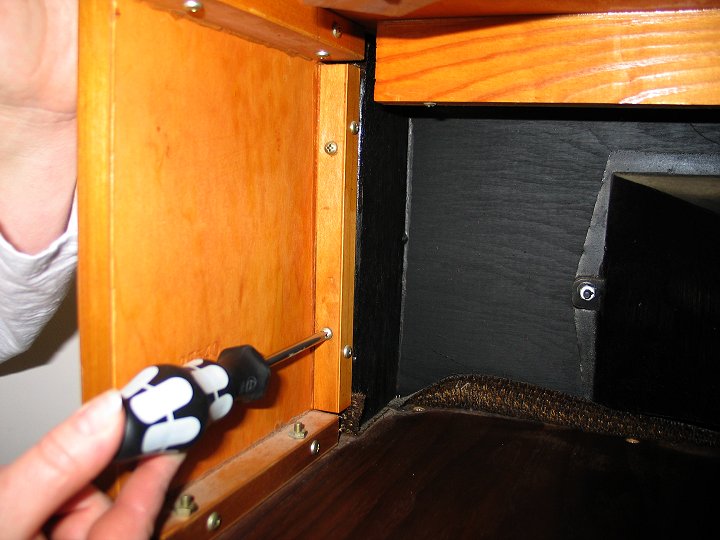
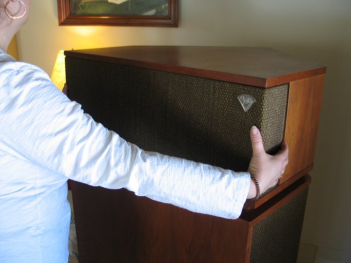
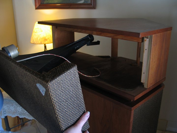
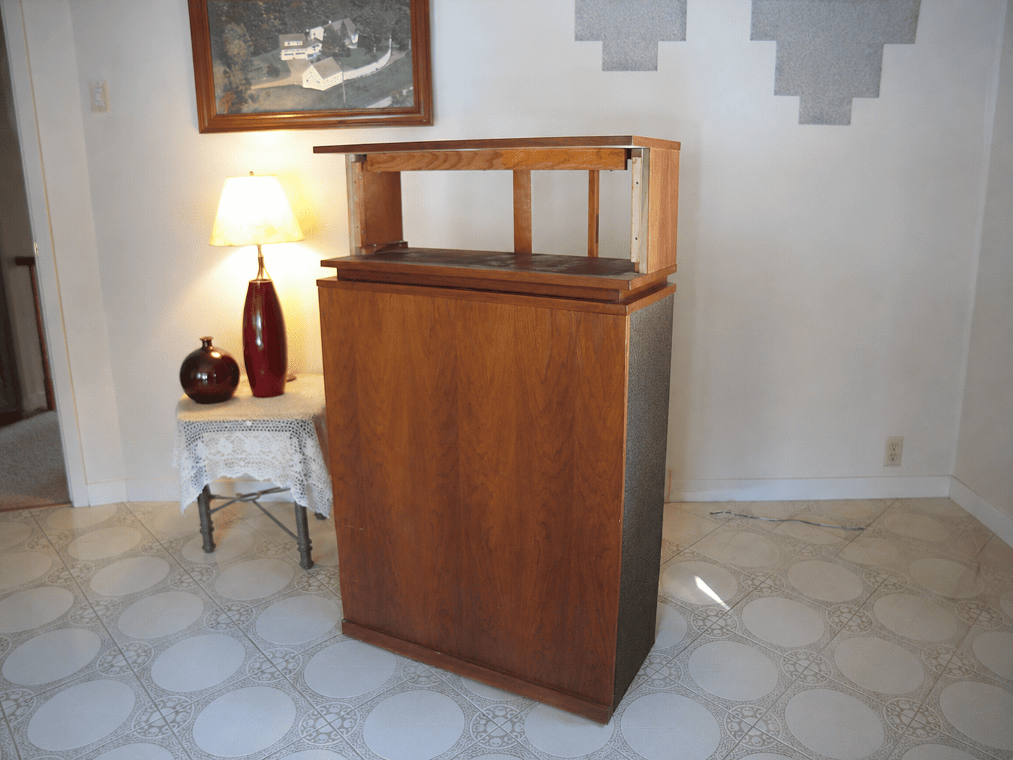
Remove the four screws that hold the midrange horn/grill frame assembly to the top cabinet side pieces. The midrange horn is attached to a plywood frame that also holds the tweeter and is covered with grill cloth. This whole assembly is held in place by four screws. Once these four screws are removed, the assembly will loosen and slide out the front of the cabinet. Remove this assembly carefully, being sure not to damage the wood cabinet with the back of the midrange horn.
Belle owners – it is probably easier to remove the top of the cabinet first, before taking the screws out of the side pieces that hold the front grill frame/mid horn assembly. You do this by removing the four screws that screw up into the top from the cleats on the side pieces.
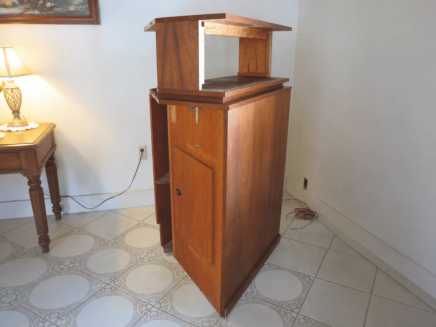
05
Remove the three screws that hold the upper brace underneath the top of the cabinet. Remove the brace (may take some force to loosen it). It may be possible to re-installed this brace farther back on the tophat and still fit the V-TracII horns in place, but I have never found the brace to be necessary and I recommend removing it completely.
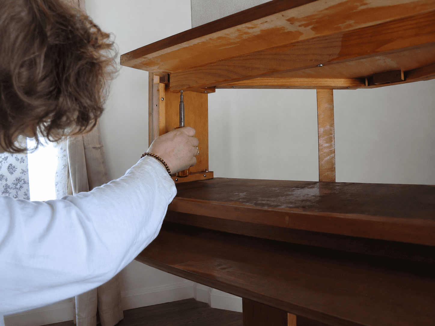
06
A pair of V-TracII horns are built so that one is a right and the other a left. We recommend locating the tweeters outside of the midrange horns – so facing both speakers, the right tweeter is to the right of the mid horn and the left is to the left of the mid horn. You will need to remove one of the back vertical braces on each speaker – the one on each speaker that will interfere with the mid horn.
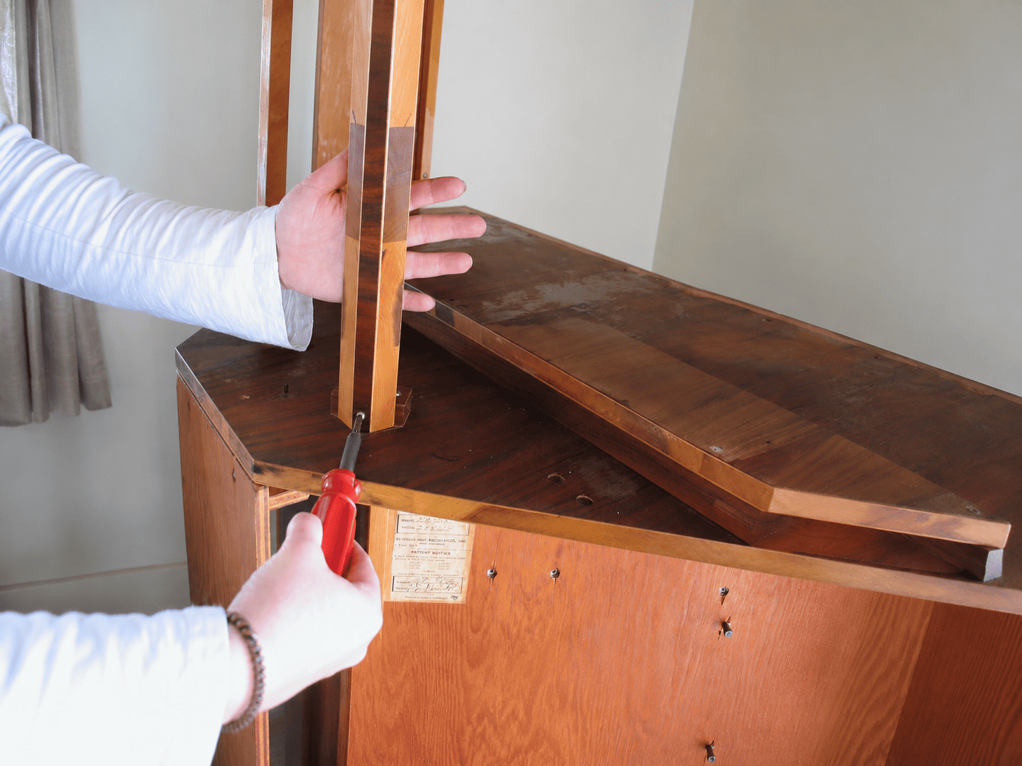
07
Now the disassembly is complete (except for woofers), and this is a good time to clean the upper cabinet and move all the old parts out of the way into another room so you’ve got plenty of room to work with the new components.
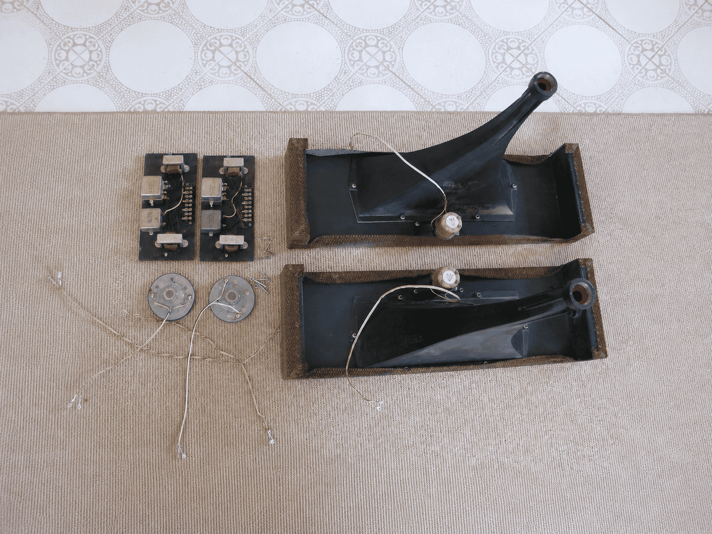
Prepare The V-Trac Horn/frame Assembly
01
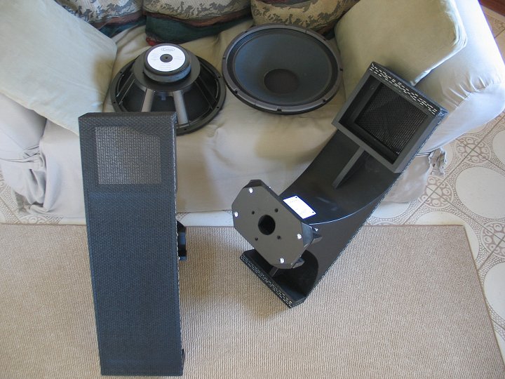
Lay both horn/frames on their fronts on a clean, soft surface (towel on a table for instance). Find the tweeter motorboards and take a few minutes to learn how these motorboards go in place, their orientation, and how the tweeters are mounted to them. Note that there are pre-drilled holes on one side of the tweeter motorboards for mounting the tweeters. The tweeter motorboards only go into the frame in one direction, with the tweeter mounting holes facing forward (down at this point). They slip in under the outside edge of the frame and then drop in place. You should see three mounting screw holes through each motorboard and three corresponding holes in the frame. The holes going through the motorboard that are used for mounting them to the frame are at an angle so the screws angle into the frame for a better connection.
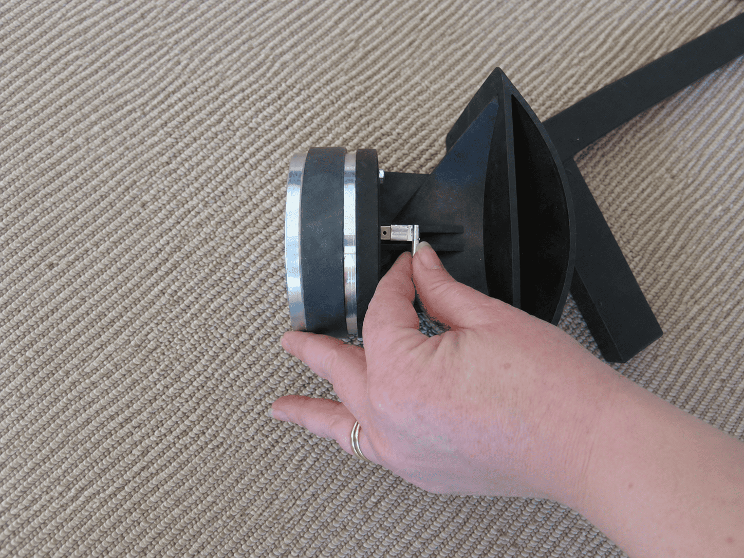
I find that it’s easier to attach the wires to the tweeters before mounting them to the motorboards.
02
Holding the motorboards in the proper orientation, drop the tweeter wires down through the motorboards and attach the tweeters to the motorboards with the small black screws provided. The tweeters should end up on the front of the motorboards, facing out of the front of the grill frame.
03
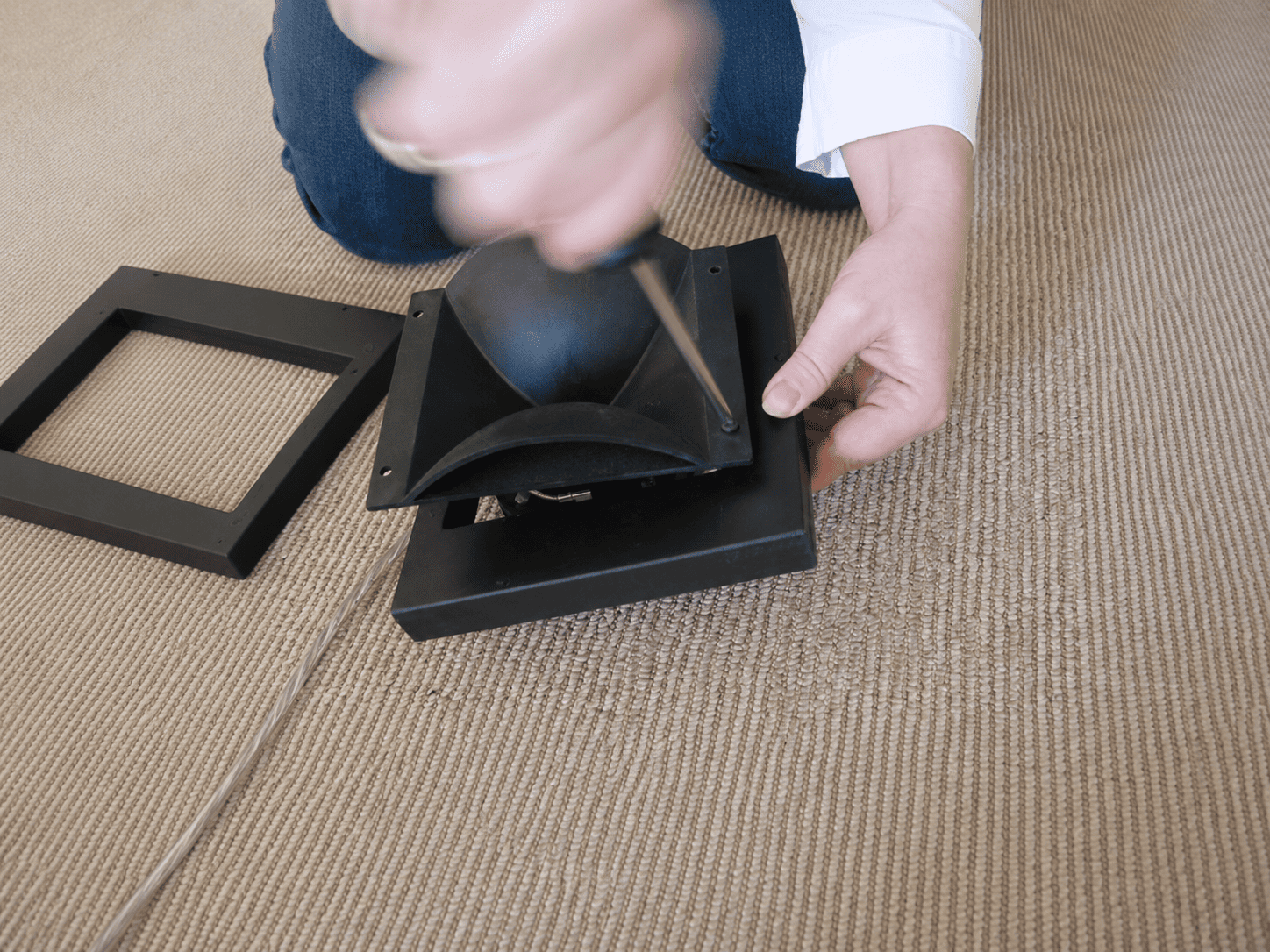
Now mount the tweeters/motorboard into the frame and secure with three black screws provided. These look like drywall screws, but they are not, they are made for fast connections to particle board, and I find they work great for plywood as well. There are six screws provided for the two tweeter motorboards, and eight screws to replace the factory screws for mounting the horn assemblies into the cabinets. Note that the tweeter motorboards are centered in the opening top to bottom, however they are pushed snug against the outside of the frame. This is how the holes were pre-drilled for them to be installed.
Midrange Motorboards
Notes:
Through the years there have been a few changes to the V-Trac midrange motorboards and how they are mounted. The first motorboards were simply bolted to the uprights that held the horn in place. Then, alignment screws and red painted dots were added that helped hold the midrange motorboard properly aligned with the throat of the horn. The most recent change occured when we developed the V-TracII horns in 2017. These newest horns have a motorboard that is screwed in place and does NOT need to be removed in order to attach the midrange driver. The advantage with these is that the manufacturing process is more refined, and there’s a much more precise transition between the outlet of the driver the throat of the horn.
For the V-TracII horns, the motorboard does NOT need to be removed from the horn to install the midrange driver. simply use the alan-head screws and washers to attach the drivers to the motorboards. That’s it. Simple. And you know that the driver is perfectly aligned with the throat of the horn. Photos and information below are for the older style V-Trac horns.
Original V-Trac Horn midrange motorboard installation:
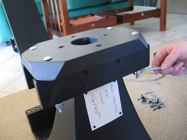
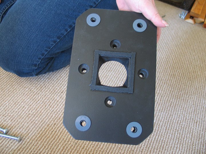
01
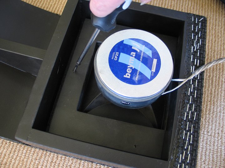
Use the machine screws and washers provided to mount the midrange driver to the motorboards. Be sure to center the driver in the hole before tightening the screws. Tighten the screws very snug so they don’t loosen up from vibrations.
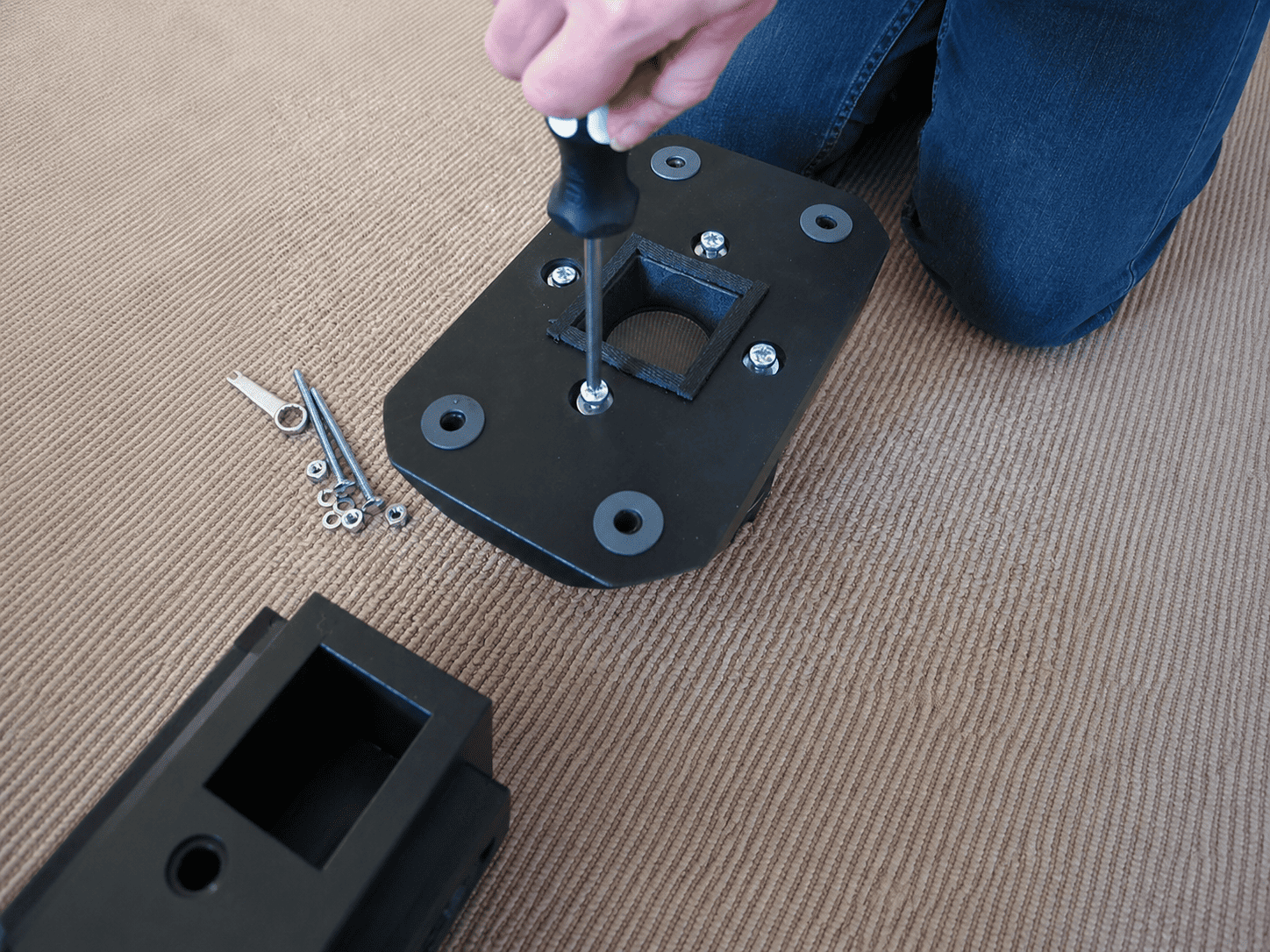
02
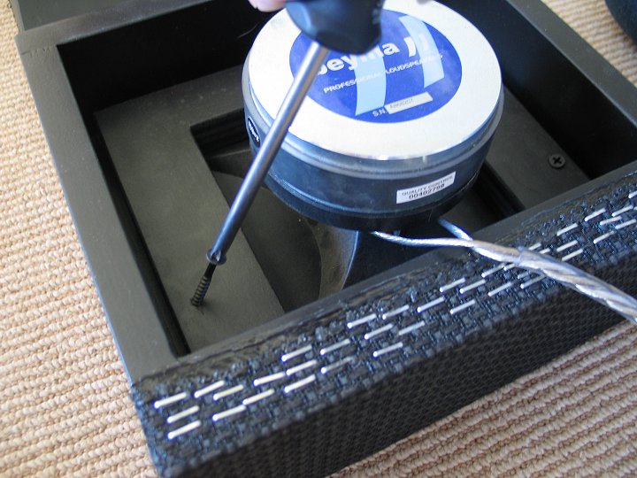
Re-install the motorboards with the drivers attached. Don’t forget the four plastic washers. Use the red paint dots on the motorboards and horns for the correct orientation of the motorboard on the horn (top/bottom). Install the four bolts down through the motorboard, but don’t install the washers or nuts at this time. Install the two alignment screws through the motorboards and into the horn frame. This will align the motorboard so that the throat of the motorboard and driver is perfectly aligned with the throat of the horn. Then go ahead and install the washers and nuts, and tighten down the bolts.
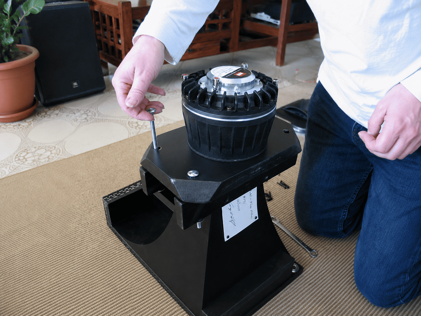
03
Apply felts to the underside of the upright supports, but locate them towards the fronts of the supports as shown in the picture. These supports support the weight of the back of the horn inside the cabinet. Apply felts to the top and bottom of the horns. It’s usually best to install them over the grill cloth, but not where the grill cloth is folded on the corners – as shown in the picture.
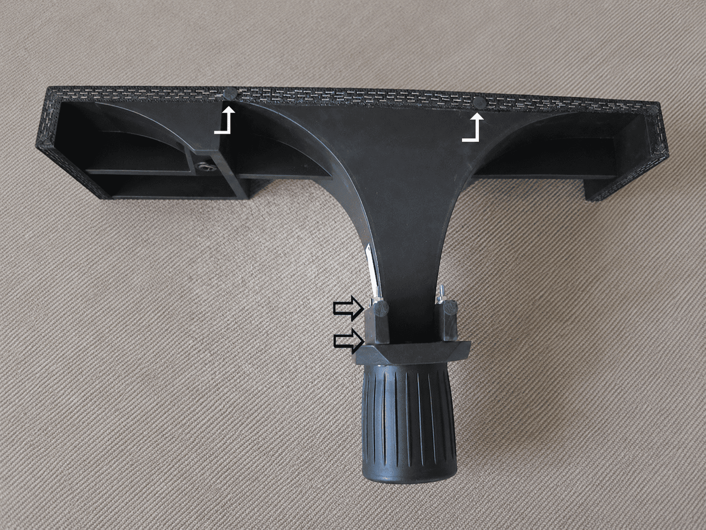
Now the horn/grill frame assembly is ready to be installed in the cabinet.
Install The Parts
01
We recommend that you install your V-Trac horns so that the tweeters are located on the outside of each speaker – that is outside of the midrange horn. Feel free to experiment with the tweeters on the inside and let us know what you experience. We prefer the sound of the tweeters being outside the midrange horns.
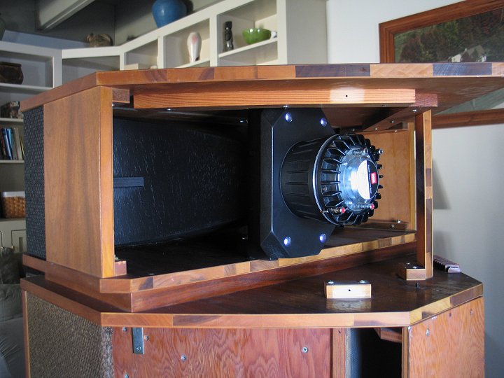
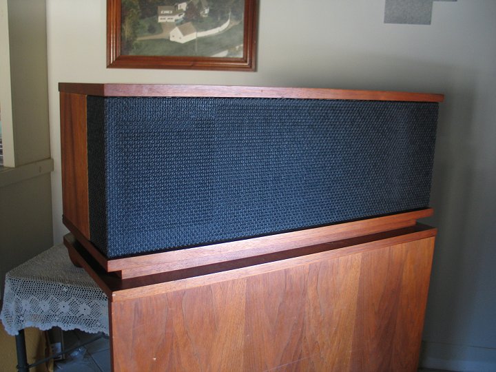
Gently push the horn/grill frame assembly into the front of the cabinet and slide it through until the fronts slip in under the top of the cabinet. It may be a tight fit, and you may need to keep the felts from folding over as you slide it in place.
On some Khorns, the rear braces on the underside of the top interfere with the horn/grill assembly and keep you from being able to center the assembly in the tophat. If this is the case, you’ll need to whittle away a bit of the corner of that brace that is hitting the midrange motorboard on the V-Trac horn until the horn/grill frame is comfortably able to be centered in the tophat. Mark with a pencil, pull the horn out a little, and whittle away the wood with a knife.
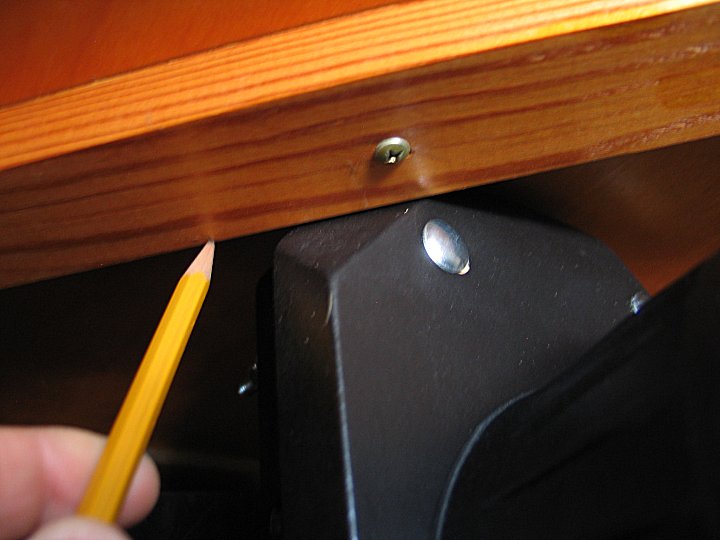
02
V-TracII horns should not have the problem of interfering with the rear braces or cleats. However, not all Khorns were built exactly the same over the decades, so there may be a rare case where the V-TracII horn does in actually hit against one of the wood pieces in the tophat. If this happens to you, please let me know, as I am curious about such things.
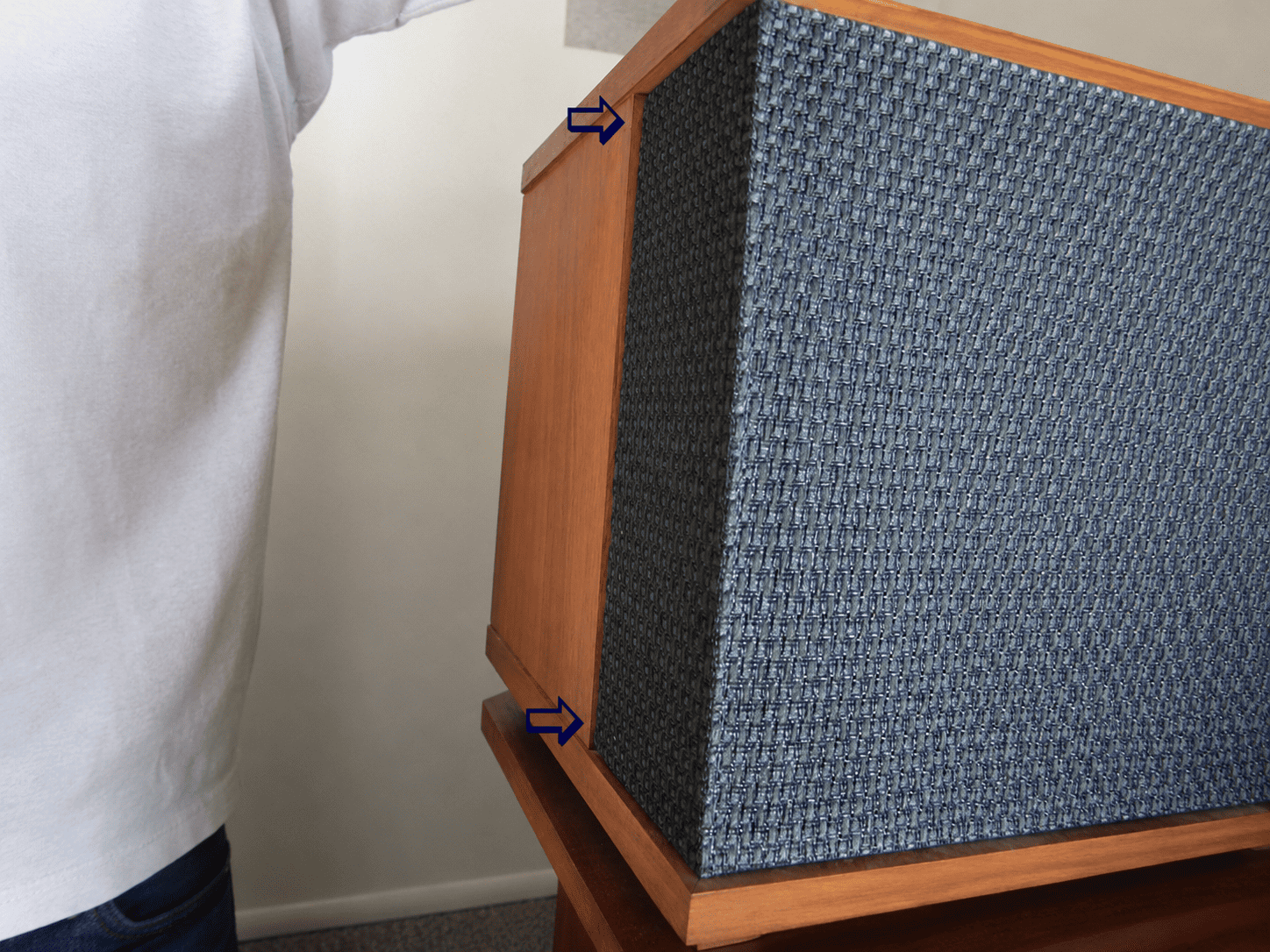
Before screwing the new screws through the four holes in the side pieces and into the new frame assembly, it is very important to line up those side pieces with the side of the horn assembly. You’ll find that you will need to tap and adjust the horn assembly from side to side, but you also may need to adjust the top of the speaker from side to side to keep the sides of the cabinet from being crooked with the sides of the horns. See the photo (with arrows) that shows how the wood sides of the cabinet may not line up with the cloth sides of the horns.
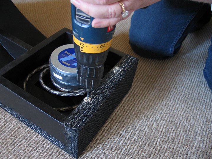
Once everything is lined up properly, start all four screws into the horn/grill frame assembly. Me? I just muscle the screws into the new frame until they are tight. But this may not be comfortable for everyone. Alternately you may want to pre-drill holes in the frame for the screws to screw into. To do this, start all four screws part way into the frame to mark the locations of the screws, and then back them out, take the frame out and carefully pre-drill the holes in those locations marked by starting the screws. Then put the frame back in and drive the screws home.
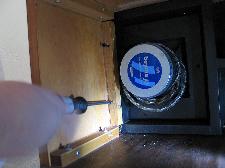
03
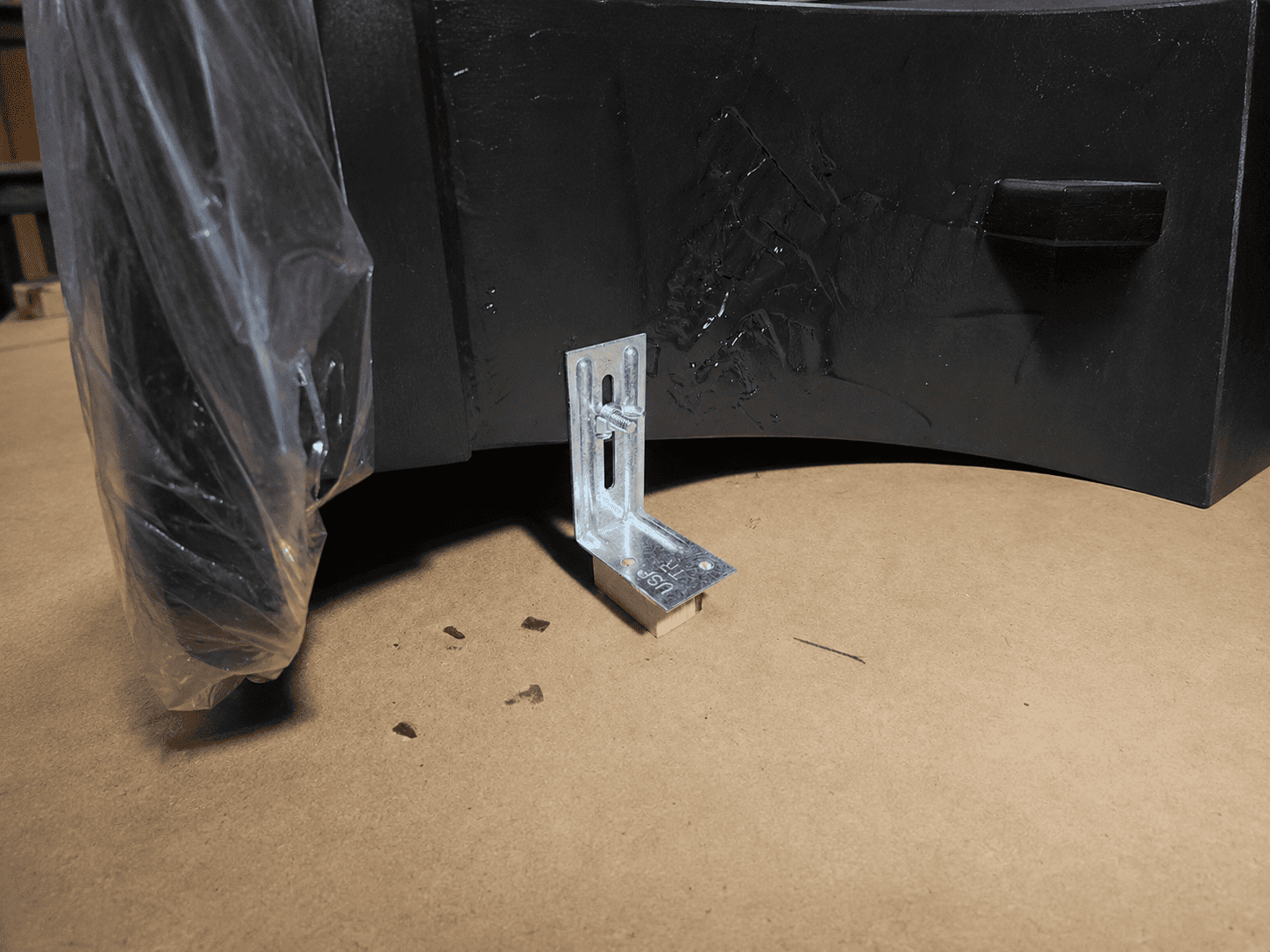
The V-TracII horn comes with a metal foot that connects to the side of the horn at the back via a threaded stud installed in the horn and a wing nut to secure it. Note that the foot has a wood block underneath it. You may choose to put a felt under this wood foot. Use the foot to take a little weight off the back of the horn, which also takes a little pressure off the screws holding the horn to the speaker sides, and once adjusted, tighten the wing nut to hold it securely.
Install the new crossovers
01
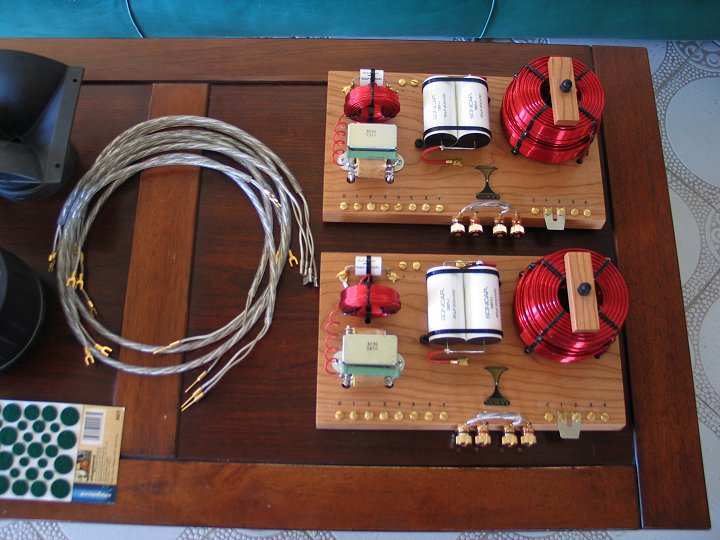
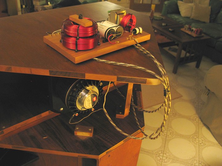
The new crossovers do not need to be screwed into the cabinet. They have sticky urethane feet on the bottom and can sit inside the back of the cabinet.
You should always remove the old crossover from the speaker path. In some speakers, crossover parts are inside the woofer chamber.
If that is the case, bypass those parts when upgrading to the new crossover network. Connect the positive and negative woofer wires directly from the banana jack connector to the woofer.
If you did not order a wiring kit, you will need to make one longer woofer wire for one speaker. The new crossover usually sits on one side of the cabinet, so one woofer wire may need to be longer.
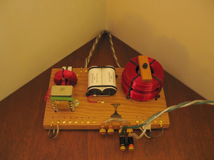
With new wiring, you can place the crossovers on top of the cabinets as I do. This also makes future adjustments easier.
If you are using the old wiring, make sure it is in good condition. Clean the wire ends so they make a strong connection.
Connect the tweeter wires to the tweeter connections on the crossovers. Be careful to keep the polarity correct for both speakers.
Connect the midrange drivers to the midrange output on the crossovers. Then connect the woofer wires to the woofer output on the crossovers.
Polarity must match on both speakers. Check everything carefully before closing the cabinets.
02
Don’t forget the badges!
When you push the Khorns back into the corners, make sure they are as tight as possible to the walls.
If you have any questions or problems with your installation, please don’t hesitate to send me an email or call me. My phone number is on your invoice.
Woofers
01
If you’re replacing woofers, you’ll need a soldering iron and possibly longer screws for mounting the woofers.
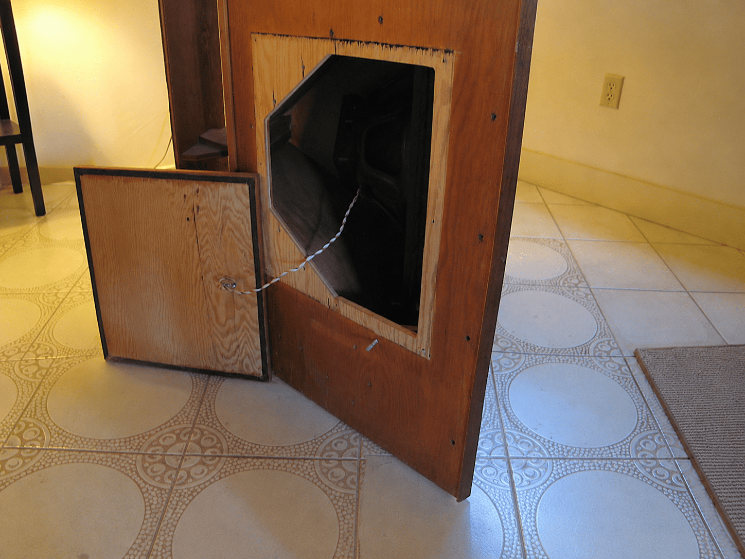
Remove the woofer chamber door, being careful not to pull the wire from the woofer inside.
02
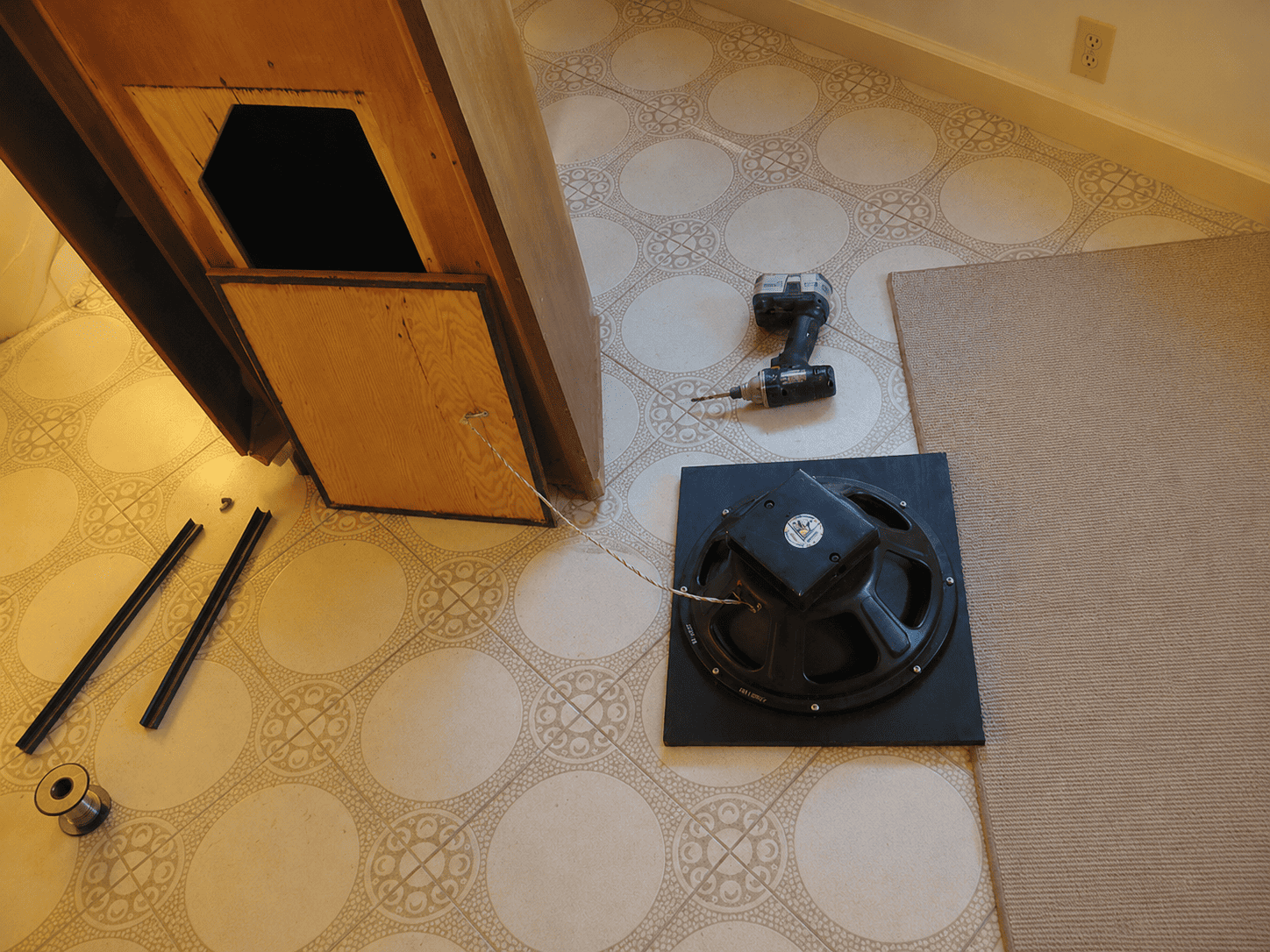
Remove the woofer from the chamber. The woofer is mounted either by four machine screws or by a removable motorboard that is mounted with metal braces and wingnuts.
03
Unsolder the wires from the woofers.
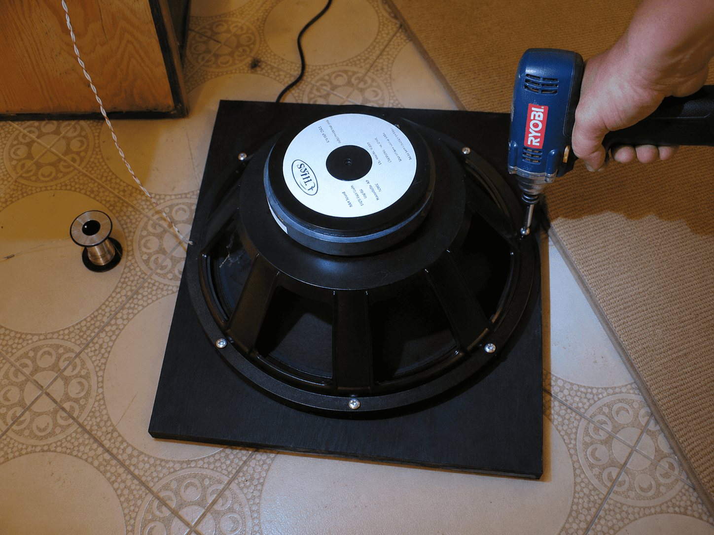
If the woofer is attached to a motorboard, remove the woofer from the motorboard. Then install the new woofer onto the motorboard.
This may require longer screws. The Crites woofers use a double gasket on the front.
04
Solder the wires onto the new woofers. Be very careful to keep the polarity correct.
The positive connection is on the outside of the woofer chamber door. Follow that wire to the inside of the door.
I recommend marking the positive connection inside the door before removing the original woofer. That makes it easier to connect the new woofer correctly.
Trust me on this. You do not want to wonder later if the woofer chamber door is closed correctly.
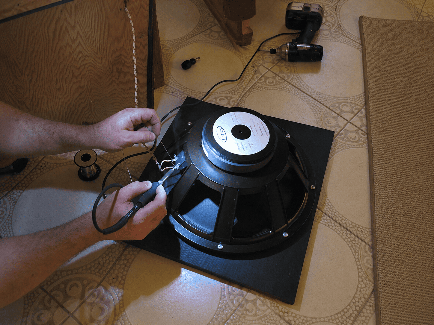
Re-install the woofer, the woofer chamber door, and the woofer wire. If you’re using machine screws to install the woofers, be sure to start those screws manually so they don’t strip. Also, don’t push in very hard when you are screwing them in. They are screwing into T-nuts, and sometimes those nuts have loosened up and will push through the back side if you push on the machine screws too hard.