
VTK CROSSOVER GUIDE
Volti Audio VTK Crossovers Installation and Adjustments
Thank you for your purchase of Volti Audio VTK Crossovers.
This page will guide you through the installation and adjustments of your crossovers.
LEGACY GUIDES
Older Crossover Installation Pages
These links are for older crossover products that are no longer sold. We keep these installation and adjustment pages available for customers who still use those crossovers.
VTK crossover networks are shipped in product-specific packaging that has proven to be very durable.
Please inspect the box and contents for shipping damage before installing anything. If you find damage, let me know right away so we can file a claim with the shipping company.
Installation
First, remove the old networks and wiring from the speakers. If you are upgrading other components, install those parts before installing the new networks.
This is also a good time to remove and clean the old wire connections on the woofer chamber door. Clean any wire terminals that have become corroded over time.
Very important for Klipsch Khorns with AK2, AK3, AK4, and AK5 crossover networks: These networks have woofer crossover components inside the woofer chamber.
I strongly recommend disconnecting those internal components when you install the new crossover. The woofer output from the new network should run directly to the woofer.
If you are not sure about this step, contact Volti Audio before operating the speakers.
Volti Audio crossovers are not screwed into the cabinets. They have sticky polyurethane feet that hold them in place inside the cabinet.
If you move the speakers, lift the crossovers out first. The feet hold well, but they should not be forced to carry the weight of the crossover during transport.
VTK Crossover Connection Path
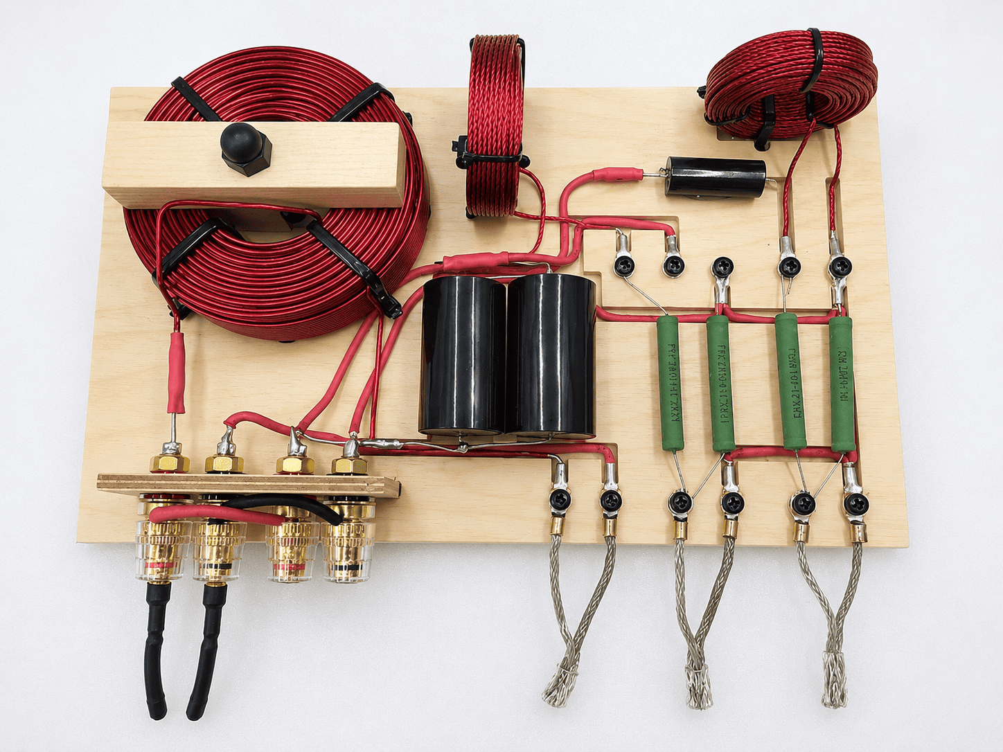
Connections are straightforward. The input from your amplifier goes to the binding posts. From there, each driver connects to the correct screw terminals on the front edge of the crossover.
Next, connect the wires coming from your amplifier to either set of binding posts. If you bi-wire, remove the jumpers and run two sets of wires from your amplifier to the crossovers.
Finally, connect the woofer, midrange, and tweeter wires to the screw terminals on the front edge of the crossover. Make sure each wire is held securely by the screw.
It is very important to make sure the polarity is correct for all of the connections. It is easier than you think to have one of the drivers wired backwards. While being wired backwards does not cause any serious damage to occur, it does interfere with the imaging, soundstage, and possibly the tonal qualities of the system.
Important note
For Klipschorns with AK2, AK3, AK4, or AK5 crossover networks, do not use the input binding posts on the woofer doors as amplifier inputs.
Instead, send the amplifier output directly into the new crossover. Then run the woofer output from the new crossover directly to the woofer.
If your speaker still has crossover components inside the woofer chamber, I recommend disconnecting those parts. If you are unsure, please contact me before operating the speakers.
Another important note
These crossovers use a simple design with very few components on purpose.
The goal is to balance and voice your Khorns so they sound their best. Also, fewer parts in the signal path can help preserve sound quality.
However, these crossovers do not protect against every possible misuse. For that reason, do not run test tones, play very loud music, or use too much power without proper protection.
Resistors
In these speakers, the midrange and tweeter are often much more sensitive than the woofer. For that reason, their output must be attenuated to balance the system.
The stock Klipsch crossovers have fixed output levels. However, the VTK crossover lets you choose the output level with resistors.
Also, the midrange and tweeter attenuation is controlled by resistors installed on the crossover board. There are separate resistor positions for midrange and tweeter output.
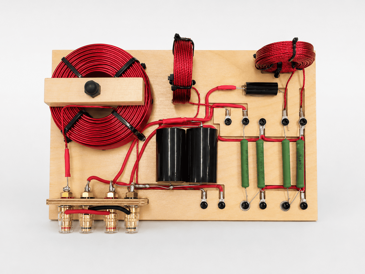
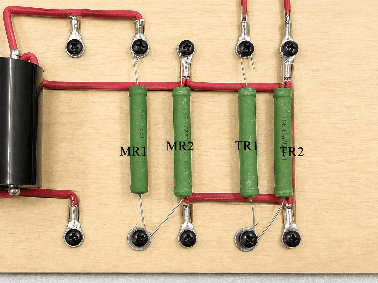
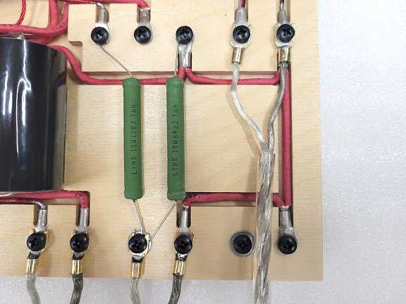
From left to right, the first resistor is Midrange Resistor 1, or MR1. The second is Midrange Resistor 2, or MR2. The third is Tweeter Resistor 1, or TR1. The fourth is Tweeter Resistor 2, or TR2.
Please take a minute to study the photos below so you can identify the resistor locations.
Here’s a closeup photo of a resistor.
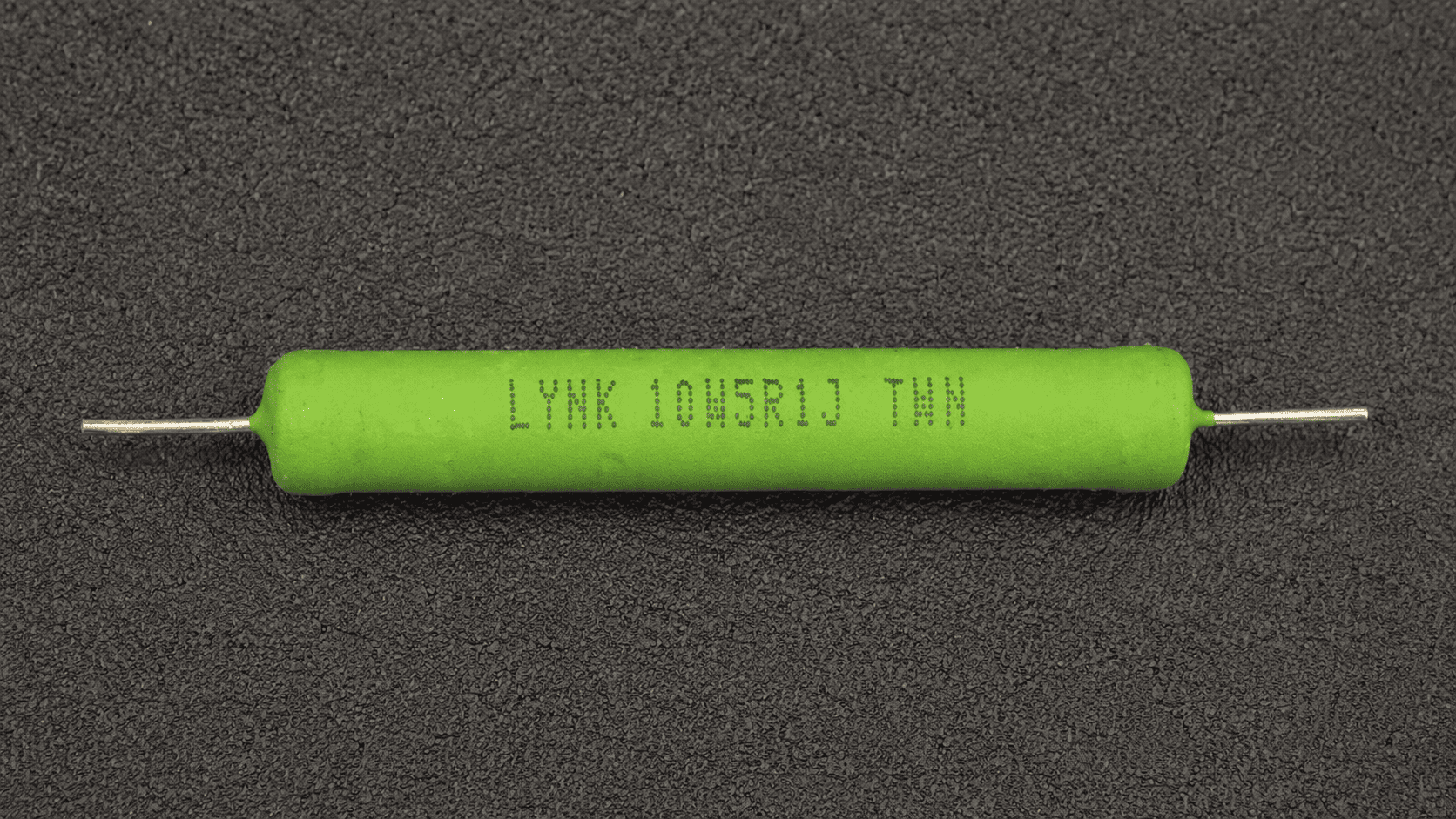
Nomenclature = “LYNK” is the brand – “10W” means 10 watt and “5R1J” means it is a 5.1ohm resistor. A 12ohm resistor would have “12R”. The 5R1, 12R, etc… is the only part that you need to identify if/when you replace any of the resistors.
Connecting the tweeter
You will always need to attenuate the midrange drivers. However, you may choose not to attenuate the tweeter at all and run it at full output.
This is common with the stock K77 tweeter. If you choose to attenuate the tweeter, install the resistors on the board in the TR1 and TR2 positions.
The photo below shows the tweeter connected to the screws with no attenuation.
Important Connection Notes Regarding Resistor Wires
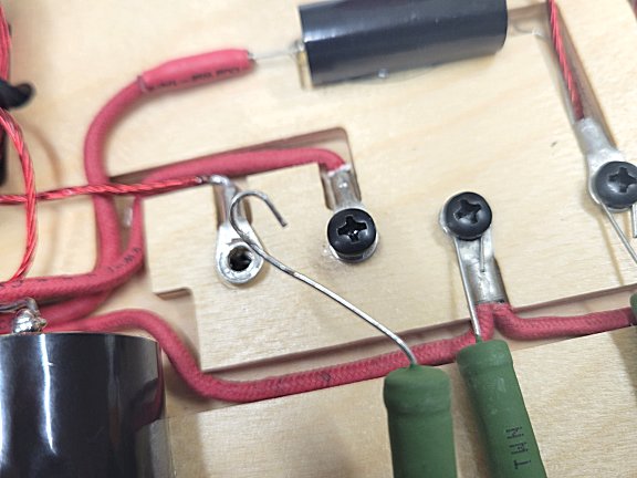
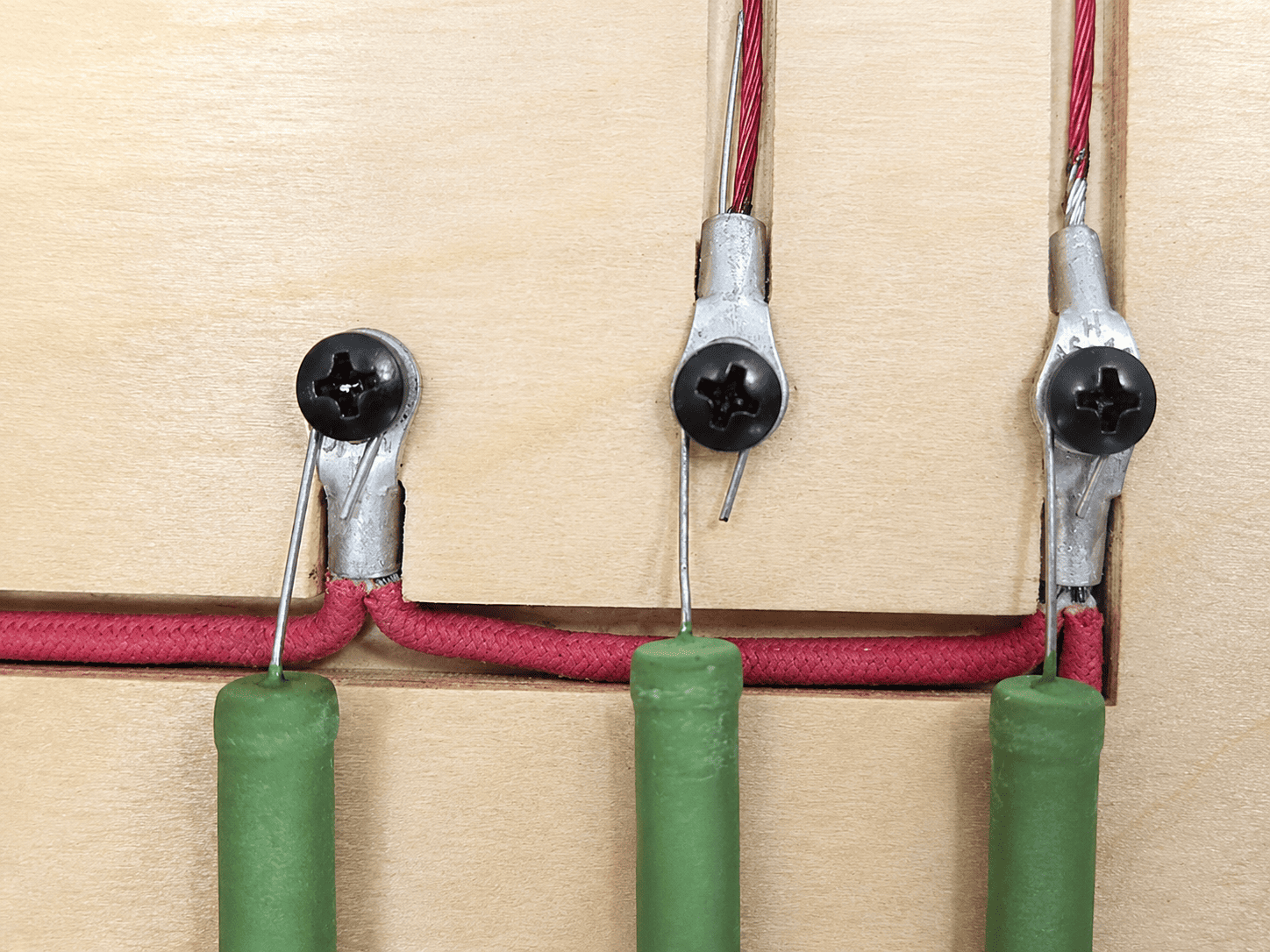
When connecting resistors or drivers to the screw terminals, make sure all wires are held securely by the screws.
First, look closely at the resistor wires as they turn around each screw. The wire should loop around the terminal instead of sitting loose beside it.
Next, check that the wire is captured under the screw head and cannot pull free. If needed, remove the screw, loop the wire again, and tighten it carefully.
Important note
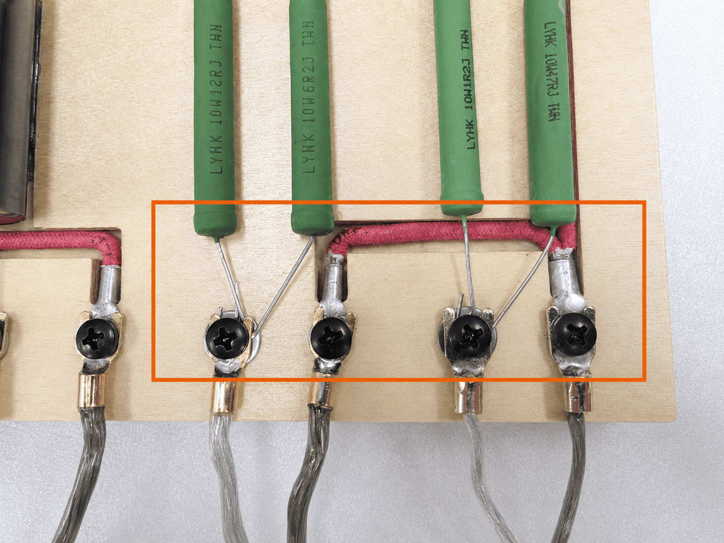
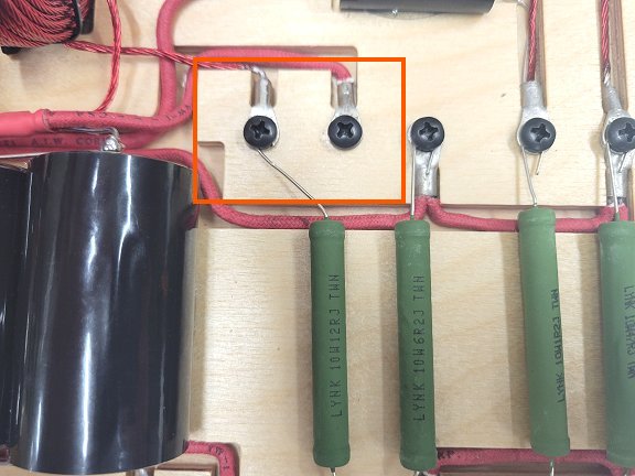
Notice how the MR2 and TR2 resistors connect to the positive output and not the negative at the front edge of the crossover? Please see the photo below and look at the area highlighted in Orange. This is a very important detail to know and understand, because it would be more intuitive to simply connect each resistor to the negative screw terminal directly in line with the resistor, and that is something you do not want to do.
Attenuating and Balancing the Output of the Midrange and Tweeter
We have covered the basic connections, resistor locations, and important details. Now you can choose the output level that gives your system the best balance.
When you ordered your VTK crossovers, I asked which midrange driver you would use. I installed the MR1 and MR2 resistors for that driver as a starting point.
After that, you can raise or lower the midrange and tweeter output by changing resistor values. For example, different resistor combinations change how the midrange and tweeter drivers blend with the woofers.
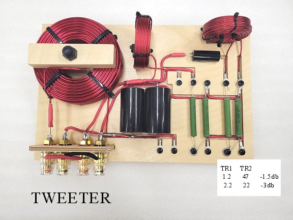
You have three tweeter output choices. First, you can run the tweeter at full output with no resistors in the TR1 and TR2 locations.
Next, you can use a -1.5db setting by installing the 1.2ohm resistor in TR1 and the 47ohm resistor in TR2.
Finally, you can use a -3db setting by installing the 2.2ohm resistor in TR1 and the 22ohm resistor in TR2. The picture below may be helpful.
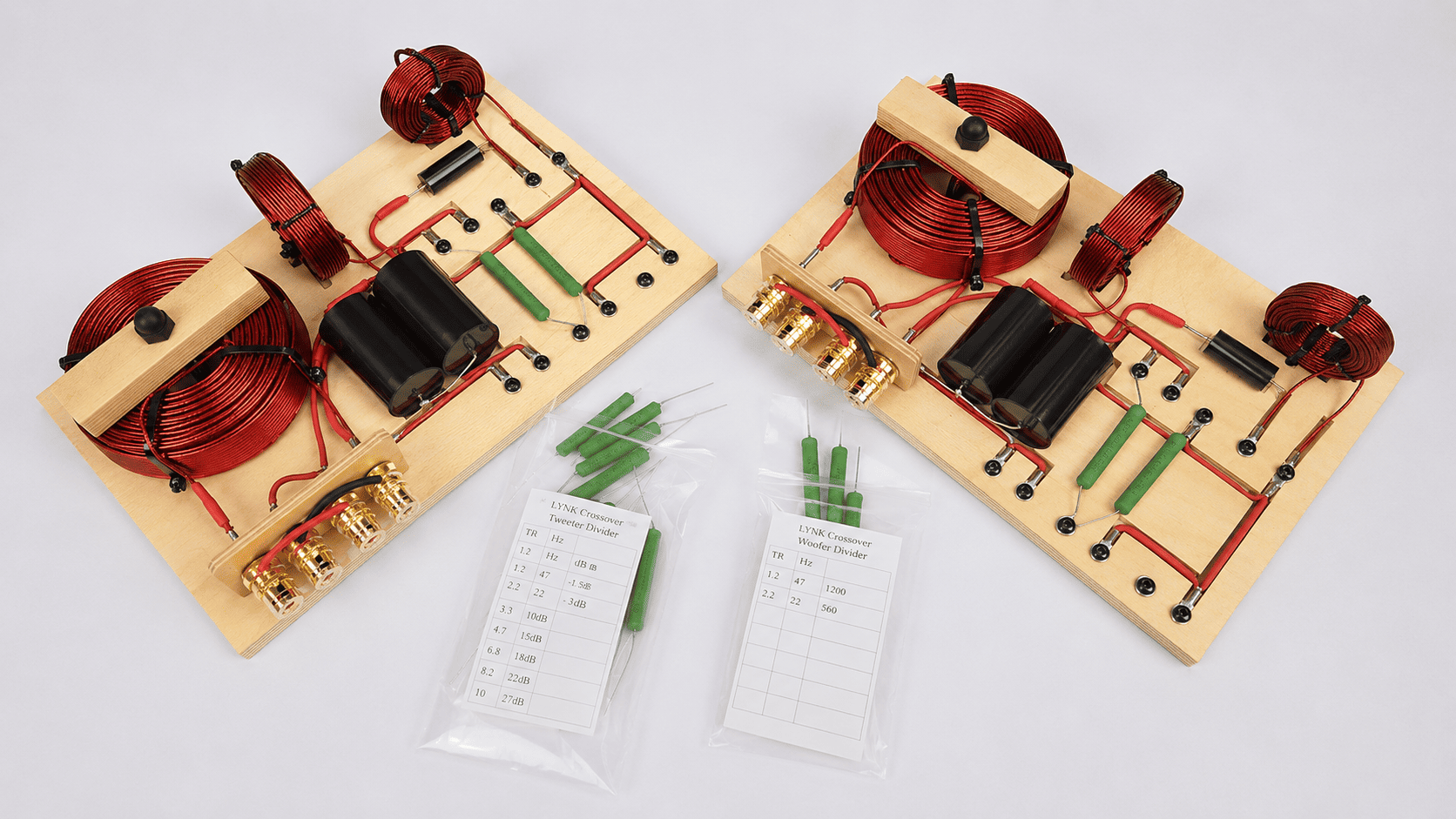
You will receive a resistor kit that corresponds to the midrange drivers you are using. Resistor combinations are different for K55 than the BMS 4592 drivers or other mid drivers.
The middle-highlighted resistor combination on each chart is the starting point for midrange attenuation. Each resistor kit gives you two higher-output choices and two lower-output choices by installing different resistors in the crossovers as noted in the charts for each driver.
The charts for K55 16ohm and BMS4592 16ohm drivers shown below.
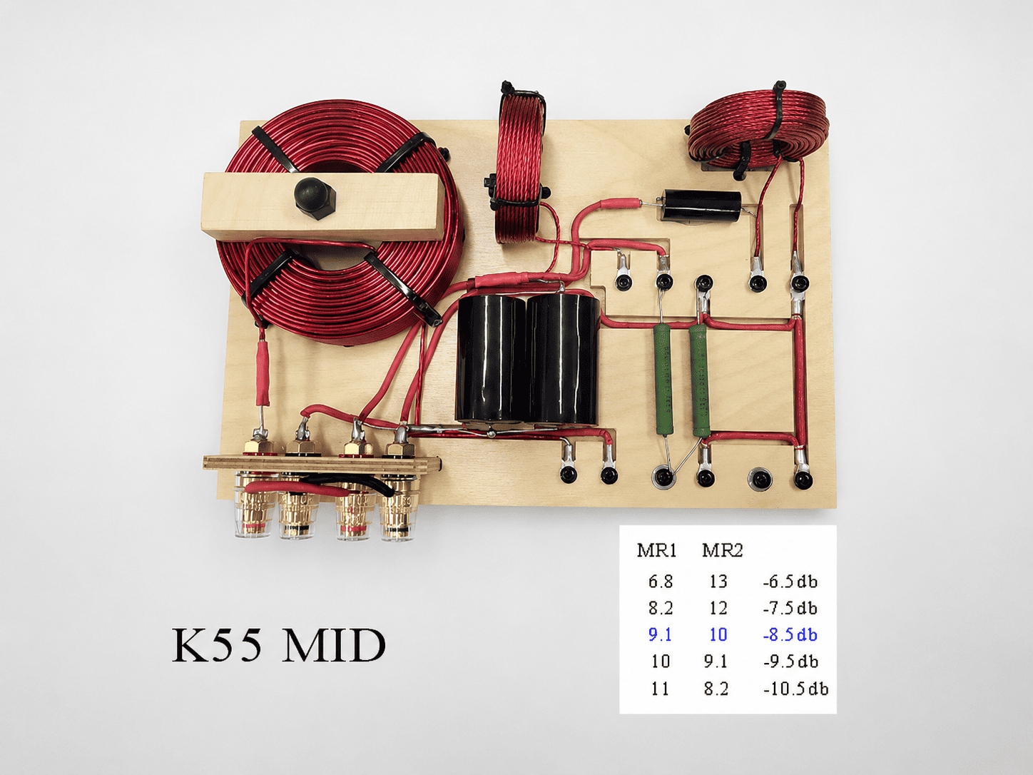

For example, if you have BMS4592 mid drivers and MR1=12ohm with MR2=6.2ohm, the setting is about -11db for the midrange.
To make the midrange louder, change MR1 from 12ohm to 11ohm and MR2 from 6.2ohm to 6.8ohm. This gives about -10db, or one db less attenuation.
You’ll find more Resistor charts at the bottom of this page.
Upper Midrange Response
You can adjust the amount of upper midrange by moving a resistor from one screw terminal to another.
Also, I offer this feature because I like the sound of both settings. Some listeners prefer one setting, while others prefer the other.
When the MR1 resistor connects to this screw terminal, the upper midrange is more present in the mix.
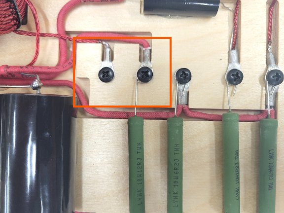
With the MR1 resistor connected to this screw terminal, the upper midrange is softened or rolled off a bit.
My Preferred Settings
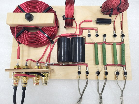
For Khorns with the full upgrade package with V-Trac midrange horns, BMS4592 midrange drivers, and Beyma CP25 tweeters:
MR1 resistor connected to the left most screw terminal for a bit of a roll-off of the upper mids.
Four resistors from left to right – MR1=12, MR2=6.2, TR1=1.2, TR2=47
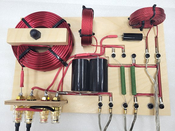
For Khorns, La Scala, Belle with stock midrange horns, K55 midrange drivers, and K77 tweeters:
MR1 resistor connected to the left most screw terminal for a bit of a roll-off of the upper mids.
Four resistors from left to right – MR1=9.1, MR2=10, TR1=none, TR2=none
Please remember that these preferred settings are simply what I prefer. You may like a different setup for your room, speakers, and taste.
That is why I offer crossovers that are adjustable. Trust your ears and have fun.
Finally, if you have any questions or problems with your installation, please contact Volti Audio before continuing.
Charts For Resistor Combinations
For BMS 4592 16ohm or B&C DCM50 8ohm on V-Trac horn
MR1 MR2
11 8.2 -9db
11 6.8 -10db
12 6.2 -11db Recommended Starting Point
12 9.1 -12db
12 4.6 -13db
For B&C DCM50 16ohm on V-Trac horn
MR1 MR2
7.5 11 -7db
9.1 10 -8db
10 9.1 -9db Recommended Starting Point
11 7.5 -10db
12 6.8 -11db
For Klipsch K55 16ohm on V-Trac horn
MR1 MR2
6.8 13 -6.5db
8.2 12 -7.5db
9.1 10 -8.5db Recommended Starting Point
10 9.1 -9.5db
11 8.2 -10.5db
8ohm Tweeter
TR1 TR2
1.2 47 -1.5db
2.2 22 -3db